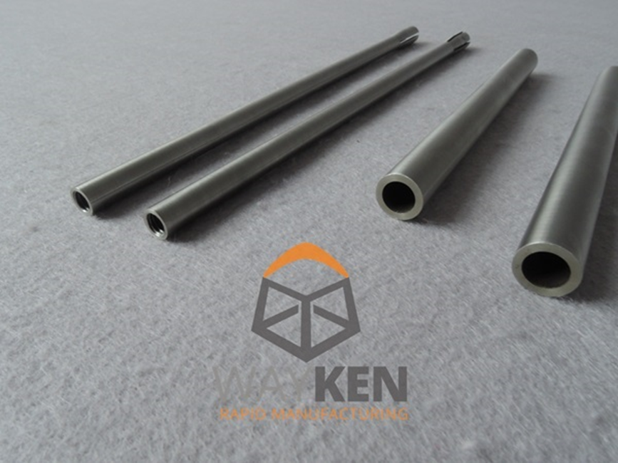
In mechanical processing, the components which are known as thin-walled parts have wall thickness less than 1mm; while slender shaft parts are those that have a length-to-diameter ratio greater than 10.
Both thin-walled and slender shaft parts lack rigidity, hence making them difficult to hold in place during turning machining; consequently they easily deform when subjected to cutting forces.
The main difficulties in machining thin-walled parts of titanium alloy with high length-to-diameter ratio are poor heat dissipation, low rigidity and weak bending resistance. Processing process by the cutting force, cutting heat and other factors, often lead to defects such as bending, tapering and barrel-shaped deformations.
For this reason, through the optimization of equipment, process plan improvement, processing parameter adjustment and deformation straightening to solve these processing difficulties.
Analysis of Machining Challenges
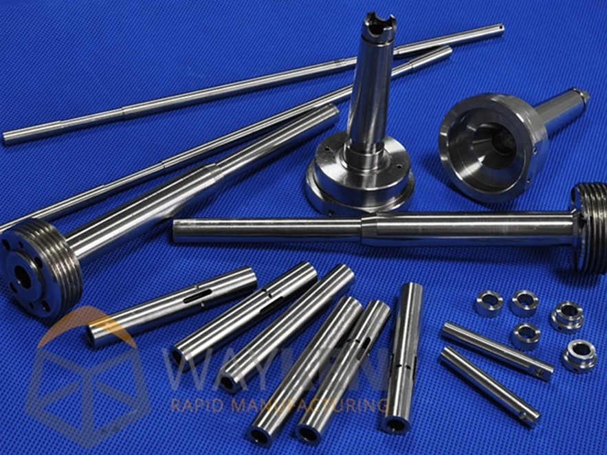
The part is simple but demanding high dimensional accuracy, as it can easily deform under clamping force and radial cutting force.
In weakly rigid thin-walled parts, plastic deformation predominates due to cutting forces during the turning machining; conversely for titanium alloy parts — with low thermal conductivity — considerable cutting temperatures induce thermal deformation during the turning process.
Not only that, but the synergy between cutting force and cutting heat acts as primary instigators for residual stress in workpieces, calling for a thorough analysis of these parameters.
The machining of parts with high length-to-diameter ratios is typically carried out using a chuck for clamping and a live center for support; in general, the installation of a steady rest or follower rest is made to balance radial cutting forces and minimize workpiece deformation during machining.
There are certain components that cannot be used with a steady rest or follower rest. This is because they do not fit due to outer diameter and length limitations. Hence, in guaranteeing the dimensional precision, measures to boost the rigidity of the clamping setup and cut down bending deformation have to be implemented.
Process Plan Design
1) The part will be given an extra 10mm space on the left along the axial direction for clamping needs. This minimizes the influence of clamping force on the external diameter’s dimensional accuracy at the clamping region.
2) Regarding CNC turning, an allowance of 0.2mm on the outer diameter of φ8mm and an allowance of 2mm on the outer diameter of φ5.4mm are suggested strategies to enhance rigidity when undergoing deep hole drilling. The turned outer diameter will play the role of positioning reference for subsequent deep hole drilling; for the inner hole, a high-precision deep hole drilling machine PT2/750 will be used to guarantee the diameter tolerance.
3) When performing CNC precision turning of the outer diameter, the use of an inner hole positioning mandrel can help improve the rigidity of the part and minimize any bending deformations that may occur. This step stands out as highly demanding among all others involved in the procedure.
4) To further elaborate on this, it is advisable to avoid any deformation resulting from cutting off the additional material by wire EDM after machining the part to its final wall thickness. After removing excess material with wire EDM, complete the task by hand filing a 0.2mm fillet to achieve R0.2mm, polishing the end face, and eliminating the electric discharge machining (EDM) affected layer.
Process Improvement
1. Equipment Optimization
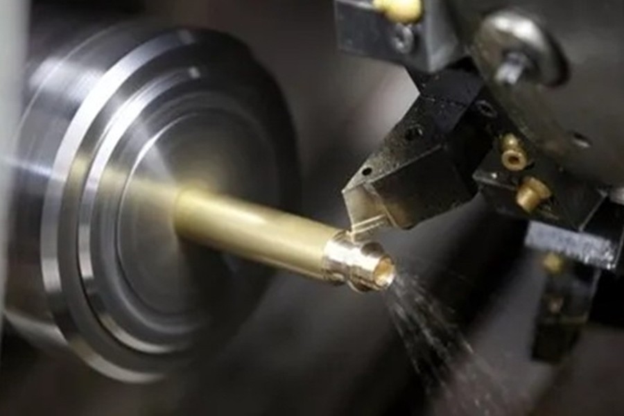
A Swiss-type lathe differs fundamentally from a conventional lathe. In the latter, machining involves moving the cutting tool to take away material. But for precision slender shaft parts, the limitations of conventional lathes are clearly manifest.
The part’s length-to-diameter ratio is almost 40, which makes it more appropriate for machining on a Swiss-type CNC lathe. When using Swiss-type lathes to machine parts, an additional length (over 200mm) should be considered for material feeding; however, traditional lathes would only require an extra 15mm length for this particular component.
Because the material is made from TC6 titanium alloy (which is costly in itself), the extra considerable length needed for Swiss-type lathe machining further escalates the cost of production— to be high. In addition, those semi-finished parts that have already undergone processing at the deep hole drilling stage cannot be tampered with once more. Hence, to resolve clamping issues during machining with a Swiss-type lathe without altering material preparation length, the steps listed below are implemented:
The Additional Position of the Part should be machined by creating an M5×0.5-6H internal thread with a 9mm thread engagement length.
In place of the additional material, design a feed rod that matches it: make the feed rod out of 45 steel, have it 240mm long with an M5×0.5-6h external thread. The outer diameter of the feed rod should correspond to the outer diameter of the part before Swiss-type lathe machining so that clamping can be achieved reliably with a spring collet.
2. Adjust Cutting Parameters
Another way to improve the surface quality and reduce tool wear is to adjust cutting parameters. TC6 titanium alloy is not easy to cut for several reasons: it does not conduct heat well, which causes high temperature in the area close to the edge when being cut; it has a high viscosity during cutting and low elastic modulus, so it tends to deform easily.
An optimization of tools and cutting parameters for machining TC6 titanium alloy through Swiss-type CNC lathe has been achieved through comparative tests on inserts from multiple brands. The process involves turning with Mitsubishi inserts under spindle speed n=900 r/min and feed rate f=0.02 mm/r.
Post-machining results in an Ra=1.6 μm surface roughness plus 0.3 mm outer diameter straightness, but it is not able to satisfy the condition of 0.1 mm straightness requirement on the outer diameter. Furthermore, ensuring φ 0.2 mm inner hole to outer diameter coaxiality is also difficult.
3. Deformation Straightening
The straightening process is a machining method to eliminate radial bending of shafts, rods and tubes. After deep hole drilling, the parts have been bent and deformed, and need to increase the straightening process. After deep hole drilling, the wall thickness of the external round allowance > 2mm, the clamp adopts the pressure point type straightening, the straightness of the parts ≤ 0.15mm.
The straightening fixture is designed to use a pressure point type of straightening. The parts are placed on a double V-shaped structure fixture for limiting, and the pressure head is designed as a bronze semi-circular ring. The bronze material is softer than titanium alloy, and the pressure head is changed to circular surface to increase the contact area.
Before straightening, first check the straightness of the outer circle and mark the bending point with a red pen before straightening. Visual inspection of the outer circle of the parts without indentation, check the outer circle of the parts, the inner hole diameter size and coaxiality to meet the requirements of the design drawings.
Summary
The article discusses the cutting difficulties of thin-walled titanium alloy parts that have a large length-to-diameter ratio. The development of a specialized feed fixture for the purpose of reducing additional material length while cutting titanium alloy parts at CNC Swiss-type machining would be very suitable since the cost of material is very high. For the cutting tools used in titanium alloy parts, along with parameters — they could be similar to those for parts made of a material with better rigidity but also made from the same material. However, it is necessary to adjust process parameters accordingly based on the specific equipment and part structure.


Become a Harlem Insider!
By submitting this form, you are consenting to receive marketing emails from: . You can revoke your consent to receive emails at any time by using the SafeUnsubscribe® link, found at the bottom of every email. Emails are serviced by Constant Contact